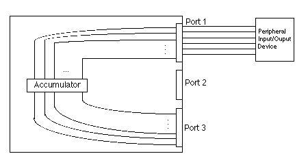
Fig. 18.1.1: Connections between the CPU and the ports, and ultimately to the peripherals
In previous chapters we studied actual I/O and secondary storage devices: tubes, tapes, disks, cards, mice, touchscreens, lightpens, ... the list seems endless. Now we will discuss how the CPU manages to collect actual values from these devices for internal storage and use.
The earliest computers had separate input and output instructions. In those days (very late 40s, early 50s) peripherals, input and output devices and secondary storage devices, were few in number and crude. Usually there was a printer and a punched card reader and a tape drive. The tape was often used for both programs and data. In fact, the essential system software managed tapes, directing when to load a particular tape on the tape drive. These were called TOS (Tape Operating Systems). Imagine how slow and clumsy they were!
Display devices (mostly printers) were minimal, too. One story tells how programmers of the Univac I tried to draw maps on a printer that printed out only numbers, not even letters or punctuation!
Consequently, those computers had a PRINT instruction and a READCARD instruction. Since computers weren't shared, no one thought of any other way of doing I/O. However, programmers noticed that the huge discrepancy between the speed of the CPU and the speed of the peripherals meant that a computer system would do a flurry of many "operate" instructions (ADD, MOV, SUB, etc.) and then it would hit an I/O instruction. The hardware would have to pause until the I/O instruction completed, usually many milliseconds later. This wasteland of time would later become a fertile prairie upon which multiprogramming would flourish.
As more peripherals were added, it soon became clumsy to have a separate instruction for each device, especially if not all computer systems were equipped with the same devices. Instructions became more abstract, mentioning only a port number instead of hard-coding whether it was a printer, a plotter or a card reader. I/O instructions became simpler, and only two, IN and OUT, were sufficient. The Intel x86 line of microprocessor chips keeps up this grand tradition, long after mainframes had moved onto grander schemes, and even today the fanciest of the Pentium chips still have an IN and an OUT instruction.
Port numbers used with IN and OUT instructions are addresses of hardware regions on a chip. They are places where internal data wires end in contact pads on the edge of the chip, to which the wires of external devices connect. An instruction such as IN 5 copies the signals on the wires connected to contact pad set number 5 into the accumulator. Some input device is physically connected to contact pad set number 5 and is setting those pads and the wires attached to them to logic values. Symmetrically, OUT 5 copies the contents of the accumulator register onto the wires that end in contact pad set 5. Any device attached to that pad set would get these logic values.
Fig. 18.1.1 shows in a very general way how I/O ports connect to peripherals. Usually ports connect to internal buses which feed the input and output wires of the accumulator.

Fig. 18.1.1: Connections between the CPU and the ports, and ultimately to the peripherals
Fig. 18.1.2 magnifies Fig. 18.1.1 to show how an individual flip-flop of the accumulator is connected to the ports. The IN command gates the value from the port to the accumulator, while the OUT command electrically connects the output of the accumulator to the port. Another complication not shown in these diagrams is that the various ports are connected by a multiplexor to a common internal bus that attaches to the accumulator. The port number which is the parameter of the IN or OUT instruction selects which port will connect to the accumulator via the multiplexor.

Fig. 18.1.2: How the ports connect to the flip-flops of the accumulator
Input and output in real systems is horrendously complicated. First of all, devices need to communicate with the CPU in both directions because control signals flowing from the CPU to the device are matched by status signals flowing from the device to the CPU. Data is flowing one way or the other, or sometimes in both directions, as in the case of devices like disk drives.
And then there's timing. Real I/O devices take various amounts of time to work and the speed of the CPU must be matched to the speed of the devices or somebody will miss the signals by latching values on wires into registers at the wrong time. Early peripherals were built specifically to match the CPUs that would be using them, but modern peripherals must work with a variety of CPUs of diverse speeds. For example, one might buy a disk drive to be used with a 486 SX computer. Later, when upgrading to a Pentium 100 MHz, that old disk drive might still be used. But simply plugging it into the motherboard of the new computer is disastrous if the speed of the controller cannot match the speed of the bus. So peripheral manufacturers put lots of "smarts" into the circuitry so that the speed can either be set manually by small dip switches or in software, usually through some sort of initialization file that writes speed values into on-board registers during boot time. The modern trend, called plug 'n' play, is to have the peripheral and the CPU and the bus do all of this automatically by sending out messages announcing their presence and their bus address, along with their operating characteristics. This trend towards more general compatibility is called interoperability since the devices can inter-operate among themselves.