|
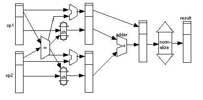
Fig. 21.8.1 shows circuitry to perform floating point addition. The two operands
are held in registers at the left end of the picture and data flows towards
the right. First, the exponents are compared using a comparator circuit
(which is just a subtractor). If necessary, one of the values must be
altered by shifting the mantissa and adding to its exponent. We don't know
which one so we have two shifters and two adders to do this. Another
possibility would have been to swap the two operands so that the smaller was
always in, say the top, register, and just that one would have been
adjusted.

Fig. 21.8.1: Hardware to do floating point addition
|
