|
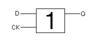
Hardware designers often abbreviate their latch diagrams as "black boxes" to abstract away all the details of NOR gates and feedback and timing. Such a diagram is called a schematic. Following are the schematics for the SR latch, D latch and clocked D latch. The value that the latch stores is often written inside the box, and the value of the outgoing Q wire is then taken to be that of what is stored inside: |

