Every memory has three sets of wires connected to it:
| data wires | the wires containing the actual data value read or written |
| address wires | the wires containing the address in binary of the desired word; this is the input to the address decoder, and causes one of the word-select wires to have 1 on it |
| control wires | the wires that select read or write and whether or not this memory is to respond to the read or write wire |
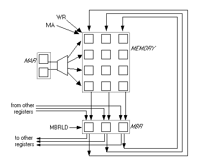
Fig. 5.10.1 shows two sets of data wires: one for input (RI's) and one for output (RO's). In reality, these wire sets are both connected to the special MBR register. Let's create a new RAM diagram that reflects this:
The output of the MBR is the input to the RAM's flip-flops, i.e. the RI wires of Fig. 5.9.1. The input to the MBR is a combination of the output of the flip-flops (the RO wires of Fig. 5.9.1) and data wires that come from the rest of the computer. These wires are attached to other registers in the CPU.
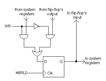
Actually, the MBR cannot really have two sets of inputs since it is made up of as many flip-flops as there are flip-flops in each memory word. Since each flip-flop has only one data input, extra AND gates are used to filter out which set of inputs the MBR should respond to. OR gates combine these filtered inputs, as shown in Fig. 5.10.2.