|
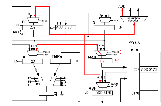
The above pictures only show in red those pathways that are of interest to us. Below is one of diagrams shown as it "really is." The output of the IR register is about to be copied into the MAR. Notice that every wire that emanates from IR is colored red and thickened a bit. These wires go into the PC's mux, A's mux, the MAR's mux, the MBR's mux and the instruction decoder. However, PC is not changed because PC-LD is not high. Neither are A or MBR changed because their LD wires are 0. Only MAR is changed. The instruction decoder is always "reading" the top 8 bits of IR and setting the appropriate instruction wire high, ADD in this case. But as long as IR's value doesn't change, it doesn't hurt anything for this decoding to happen continuously. It is important to be aware of the way things "really are," even though we ignore some of the details in order to focus on the important aspects of the instructions' actions. 
|