|
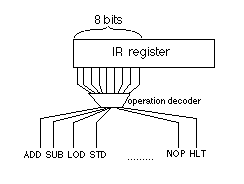
Coming out of the IR are wires that have a binary number on them, the opcode. These wires go into a decoder that sets 1 and only 1 of its outputs to 1. This output wire corresponds exactly to the one of the CSC-1's instructions, so these wires can be labeled with their machine instructions. Fig. 7.7.3 shows this decoding. Remember that the first 8 bits of the IR, not merely the first 4, determine which operation is being done. These wires are used in combination with other wires by ANDing them together to set the appropriate control points at the appropriate times. The sequencing of the DFA (this step comes after this one...) is what imparts the timing to the instruction, while the output of the operation decoder is what causes the right action to be performed. |
