|
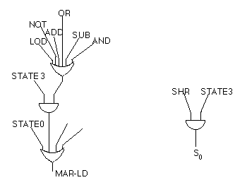
Fig. 7.8.2 shows two different control wires, S0 and MAR-LD, and how they are set. S0 is only set when the SHR (shift right logical) is executed, and then only during the execute phase of the instruction. Thus, these two wires must be ANDed together in order to set S0. Recall that SHR comes directly from the instruction decoder, as shown in Fig. 7.7.3. S0 is 0 at all other times, so the one AND gate is sufficient to give it a value.
|
